


C.a.R Firearms is a small shop that specializes in custom work and related services (think build vs. assemble) located south of Seattle. Every time I’m there I make a mess, drooling over fantastic, precision-built guns — either their creations or customer-owned.
But mostly, I enjoy visiting C.a.R Firearms because the proprietor, Fred Hastings, and his staff are solid guys. They provide one on one attention, sweat the small stuff, and work hard to deliver the very best for any customer, large or small.
Fred is a combat veteran with a professional background in CNC machining R&D. He started C.a.R. Firearms as a way to treat his PTSD. It’s wonderful to see him help himself by helping others. When Fred found out I’d never used a digital protractor for firearms, he was more than willing to share how he uses the measuring instrument to satisfy a shooter’s thirst for correcting alignment and accuracy.

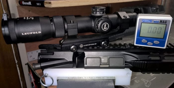
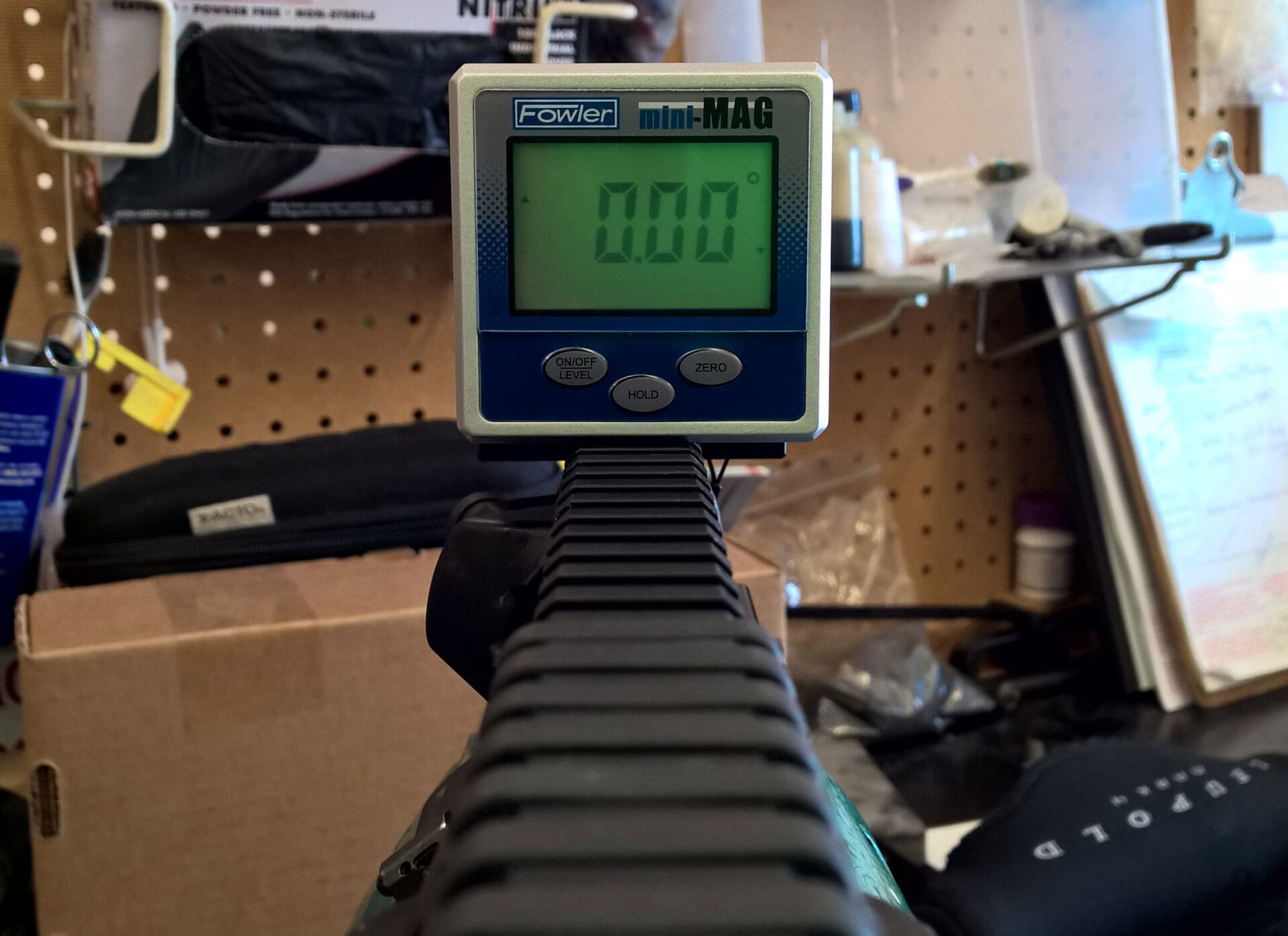
A digital protractor measures angles, with most measuring a range of 0° to 180° or 360°. The Fowler Mini-Mag measures a total of 360° by way of its four sides, each providing 90° of inclination and declination data, either relative (by zeroing off of a surface) or absolute.
On Fred’s recommendation, I picked up the Fowler Mini-Mag (above) for $63 on Amazon.
At a basic level (no pun intended) a digital protractor serves the same purpose as any bubble-level set. It simply provides a much more precise, digital reading.
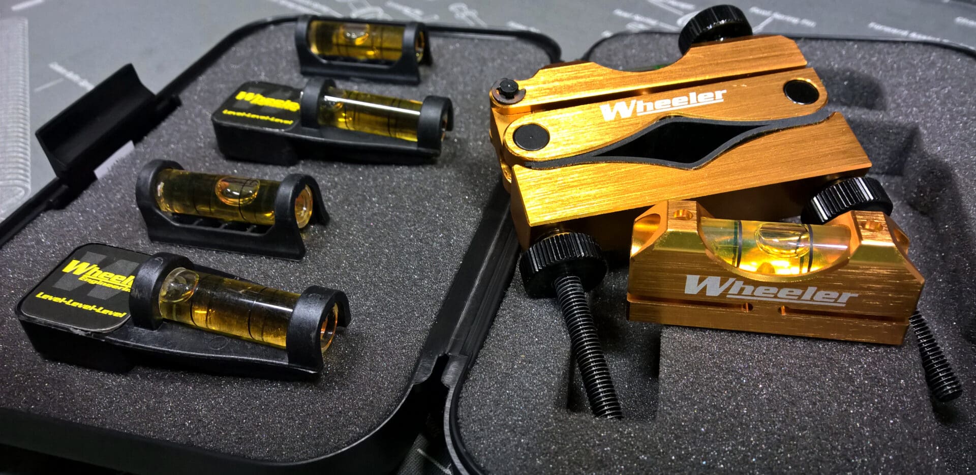
I’ve used the above Wheeler bubble levels for the past few years with decent, sometimes “perfect” results (based on double-checking with the digital protractor, of course). It must be said: in very rare instances, a clamp-on bubble level may be your only option for ensuring proper scope alignment.
The Mini-Mag has an alloy housing, 3.5 lb pull magnets on three of four sides, a large readout screen, and your standard functions (zero, hold, calibrate, etc.). Onscreen icons indicate tilt direction (up or down), low battery, and the type of reading displayed (absolute, relative, or hold).
I wish the battery panel had an O-ring seal. Anyway, in addition to a digital protractor, Fred’s scope mounting process calls for the following tools:

Aside from a vise (not pictured), the above tools are Fred’s current preferences; there are some suitable substitutions, of course (noted below). From left to right in the photo:
- Torque Wrench: Vortex Optics Torque Wrench (tube case, wrench, bits in bag)
-
Digital Protractor: Fowler Mini-Mag
-
T-Wrench: Schultz & Larsen Red Handle T-Wrench (optional if you have a toque wrench)
-
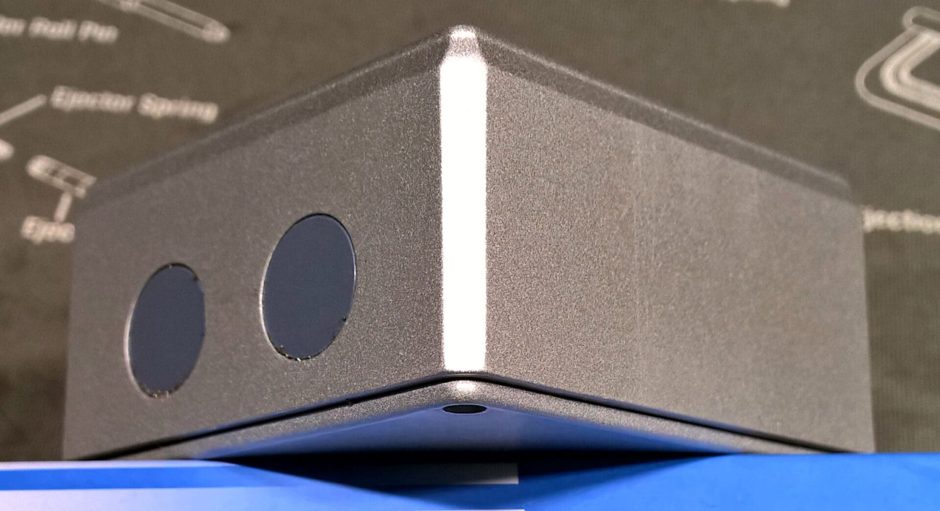
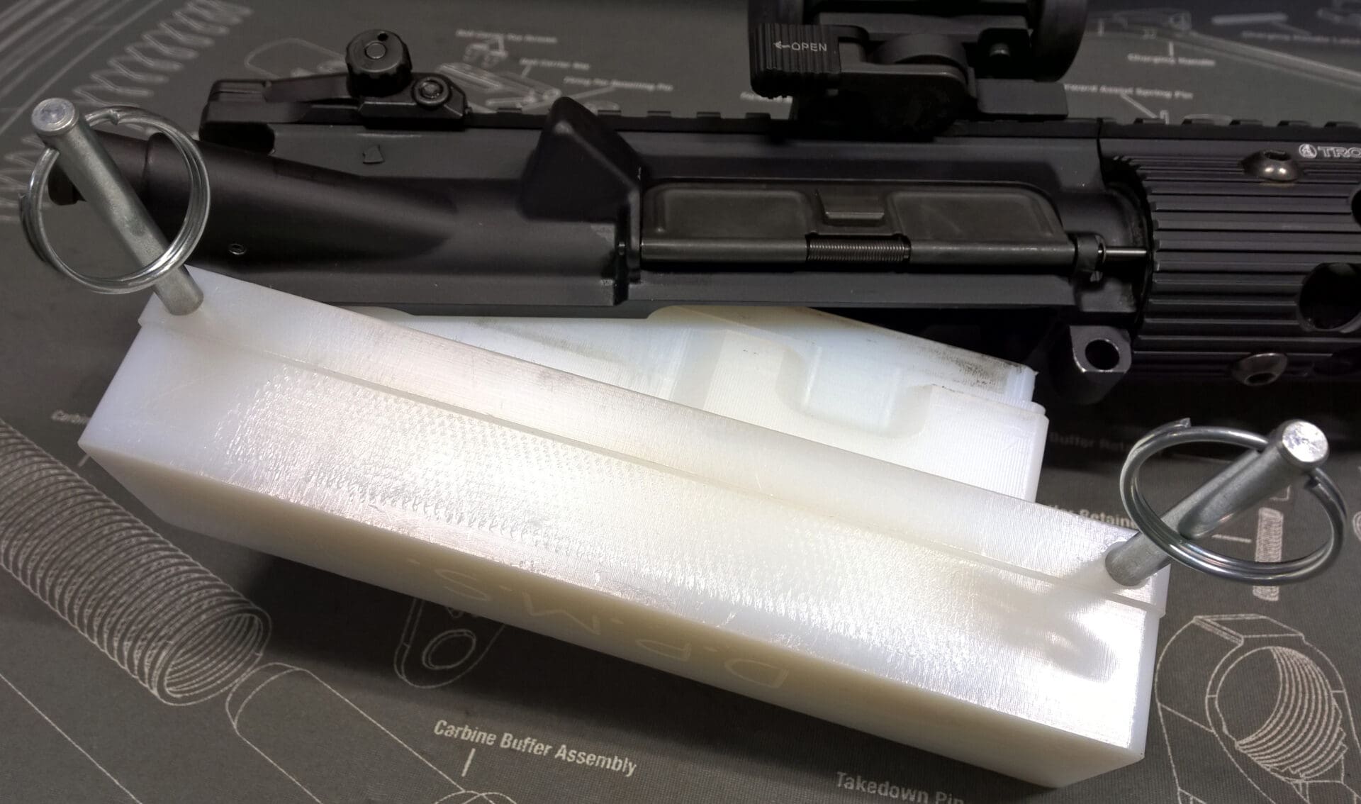
Upper Receiver Block: The Device Manufacturing AR-15/M16 Upper Receiver Fixture (2 pieces)

Regarding suitable substitutions, a Wheeler F.A.T. Wrench (above, left) or even Fix It Sticks Kit (above, right) (if you have the correct torque bit) will work just as well.
Certainly not every home shop warrants a $300 Device Manufacturing Upper Receiver Fixture. There are plenty of good, less expensive alternatives out there. I can attest that The Device’s block has far superior lock-up inside the upper receiver. It also provides a very nice rail section for mounting scopes to rings, absent a firearm.
For this process a Geissele Reaction Rod was not an acceptable alternative from Fred’s perspective. It allows for a variance of play, considering that the differences in chamber lugs and wear of those lugs can lead to a variety of tolerances.
The Scope Mounting Process
The steps outlined below assume you have already double-checked the compatibility of your optic/mount/weapon combination, lapped your rings (should you choose to do so), and mocked-up the optic on your weapon to determine proper placement with eye relief as a central consideration.
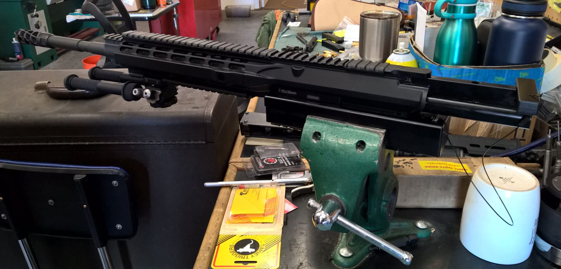
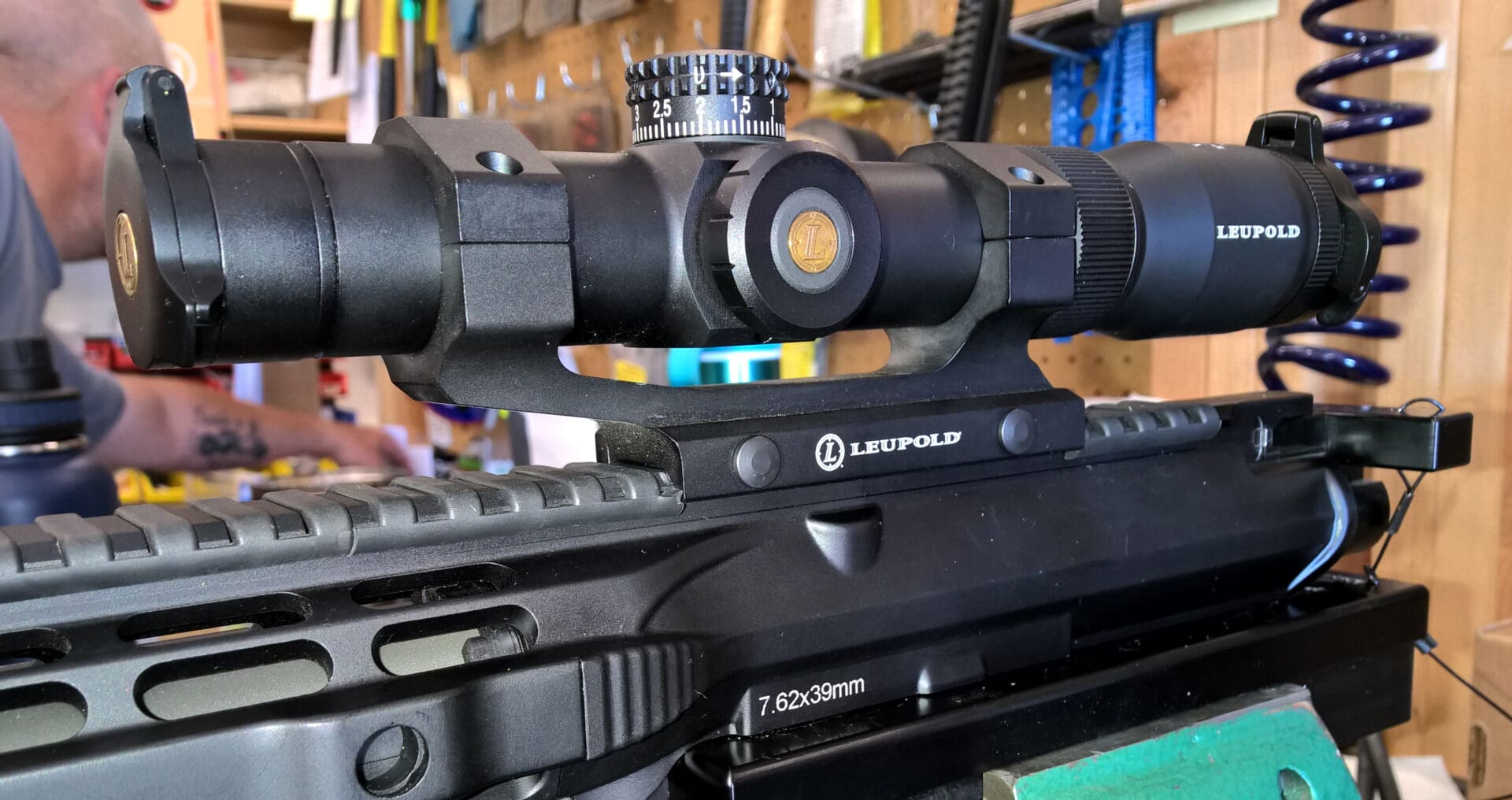
It also assumes that your optic has an appropriate vertical or horizontal flat spot from which to take a reading with the protractor. This demonstration utilizes an AR-15 style rifle, the Armalite M15A4 SPR Mod1, but is applicable to many weapon systems.
Step 1: Firmly mount your firearm to a rock-solid vice by way of an upper receiver block or other appropriate device. Ensure neither the firearm, mount, nor vice can inadvertently shift out of place during the scope mounting process.
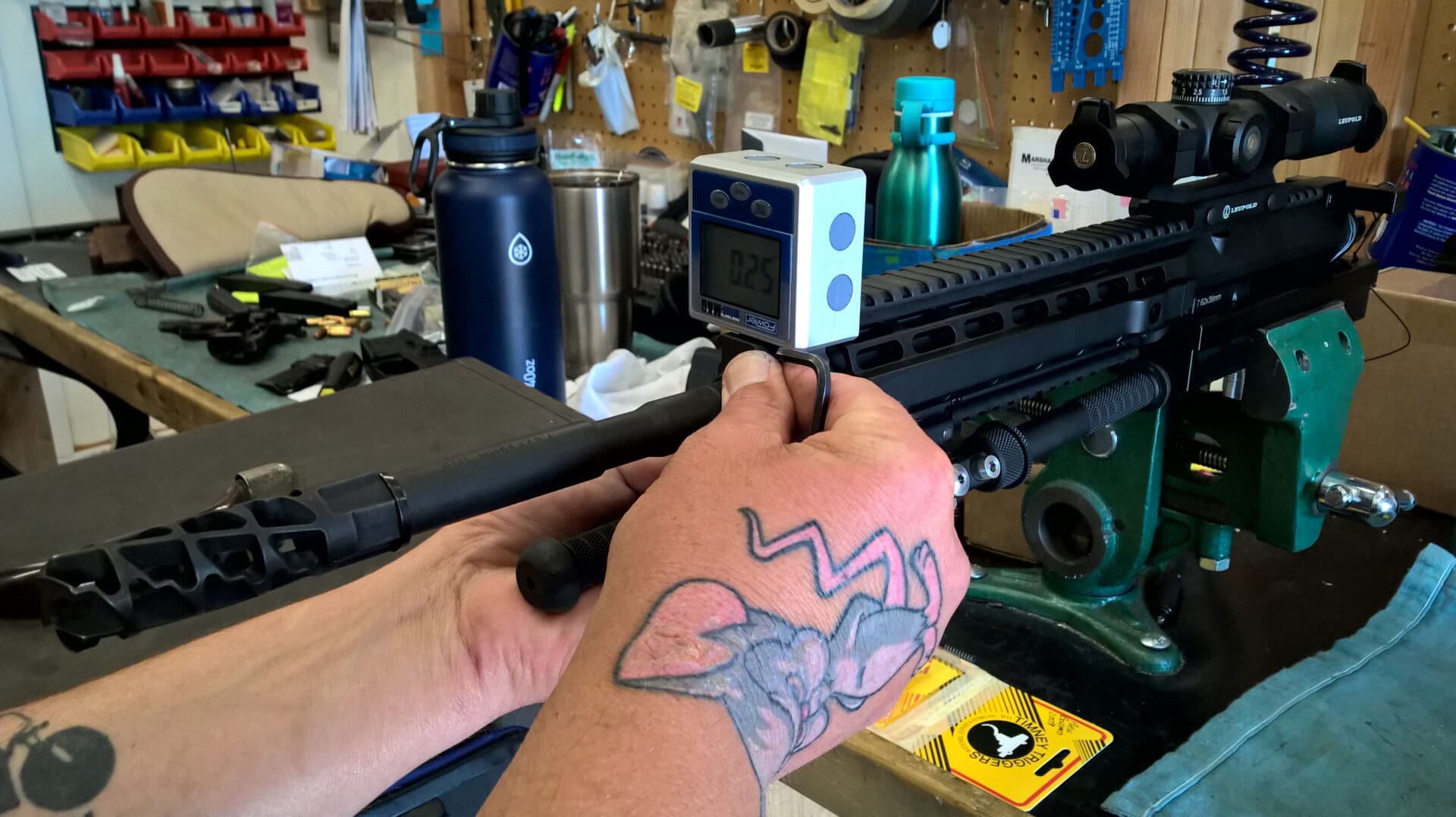
Step 2: Turn on your digital protractor and place it on a flat spot on the upper receiver (not the handguard, unless you have a monolithic upper…then maybe). This process uses relative leveling so zero-out the protractor. Check several spots along the upper receiver to ensure the integrity of the rail.
If you are using the Fowler Mini-Mag remember to keep it moving from this point on as it will reset after five minutes of no activity.

Step 3: Mount the bottom half of your rings to the rail and lock them down (consider blue Loctite 242). If you have horizontally or vertically-split rings, for kicks, take a look and see if they are level with each other. The Leupold rings above were off slightly – certainly not enough to cause worry or warrant corrective action.
Notice that Fred likes to use the protractor upside-down. He does so because the top surface of the protractor is the side with no magnets, and the buttons are easier to manipulate on top.
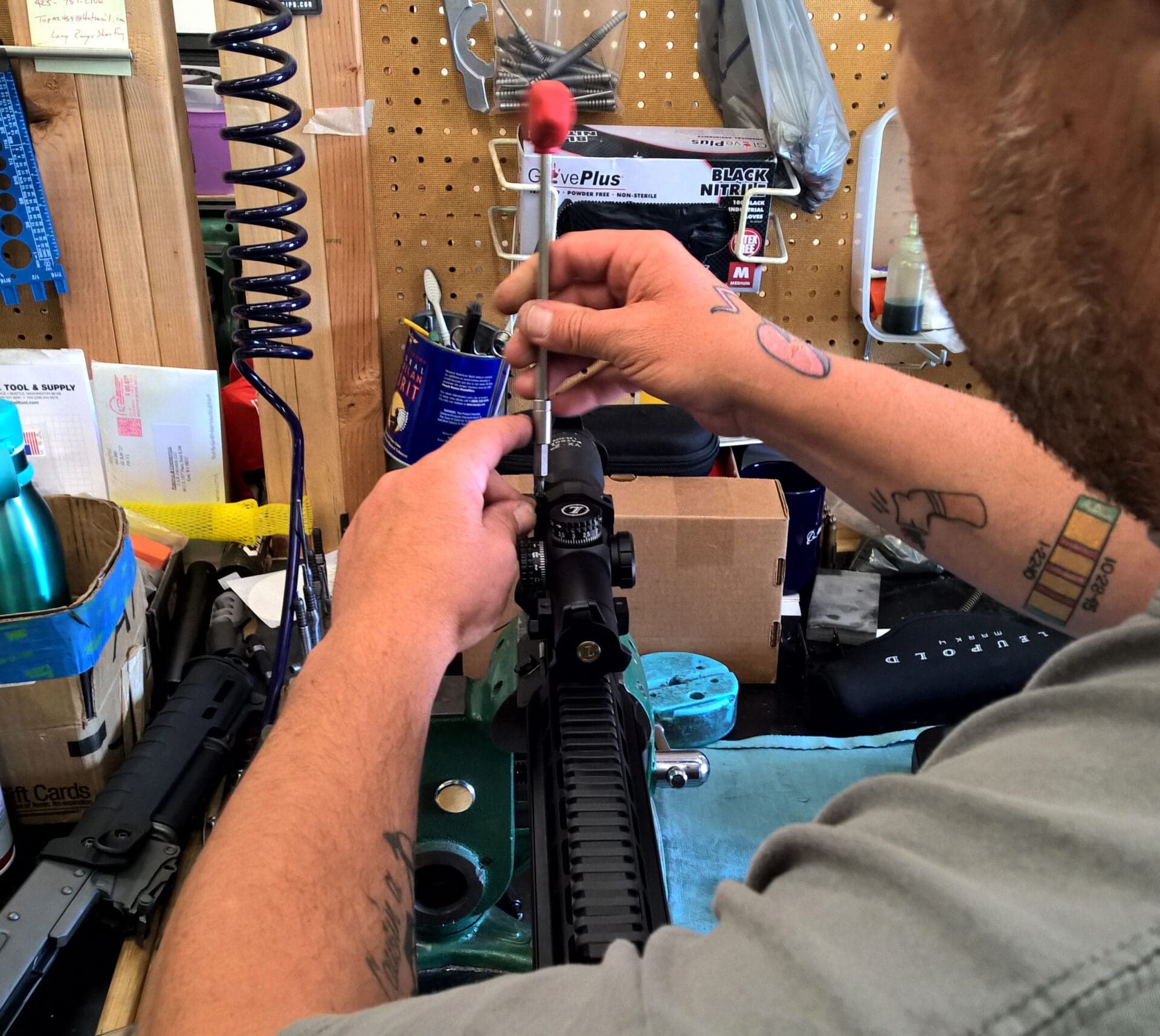
Step 4: With the t-wrench, snug your optic into the mount so that you can barely rotate it. When placing your optic in the mount, be sure to take into account your pre-calculated eye relief. Again, consider blue Loctite 242.

Step 5: Set your zeroed digital protractor onto the flat spot of your optic (most likely a turret) and slowly rotate your optic until you get triple-zeros. Your optic is now level with your upper receiver. If taking your measurement off of a side turret, simply use the side of the digital protractor – do not turn the protractor 90°.
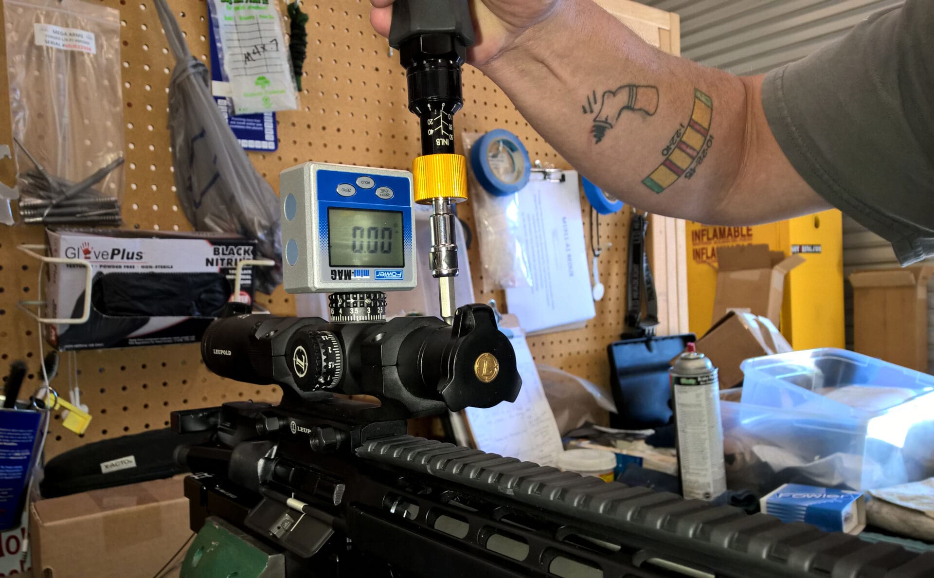
Step 6: Keeping your protractor in place to monitor change, ensure your torque wrench is set to the appropriate specification and begin slowly tightening the rings evenly and in a crossing pattern.
First, tighten until you feel resistance at each screw. Then use several passes of limited rotation to make certain the gaps between the halves of the rings are equal, until you click-off on each screw (indicating you’ve met the torque specification).
If your protractor indicates a change in the optic’s relative position to the upper’s rail, you’ll need to adjust your approach for how you tighten each individual screw, adjust the scope within the rings to compensate for the movement, or consider lapping your rings and trying again (presuming the rings are uneven and pushing the optic out of alignment).
Once you’re locked-in to specifications, remove your protractor from your optic, and then set it back down in the same spot to double-check the reading.
You can triple-check using an available pre-qualified section of rail. Look into your optic and line up the reticle with a right angle (like a door frame) and conduct a visual assessment of your reticle for proper alignment of cross-hairs or other markings, relative to the upper receiver.
The straight-forward, simple process complete, once everything checks out satisfactorily you should be set to re-assemble the firearm (if necessary) and head out to the range to dial-in the optic.
Other Handy Uses
Fred, being who he is, instinctively checked the gas block on each of the three firearms I brought in that day. Above, the Armalite’s gas block was off slightly so he took the liberty of bringing it back in-line.
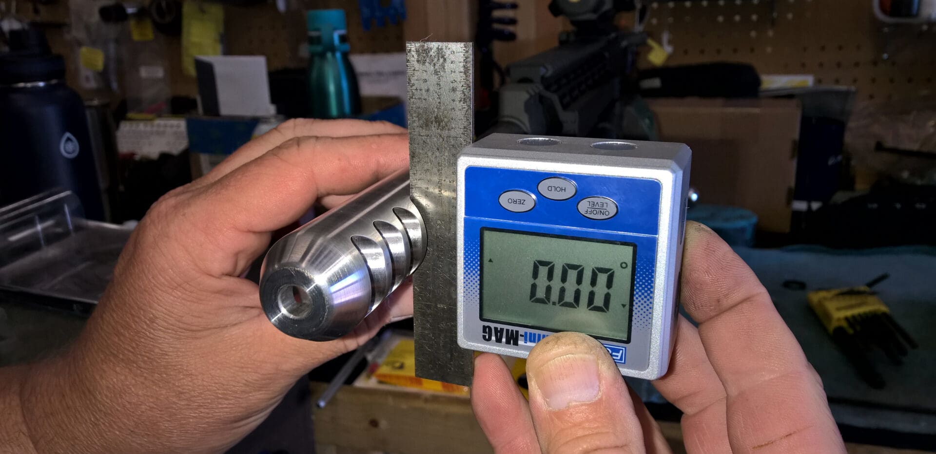
A digital protractor also works really well for timing muzzle devices. Many devices have a flat spot at the 0°, 90°, 180°, and/or 270° positions from which you can take your reading. When muzzle devices are absent a flat side, you may need to get a little creative, as demonstrated in the photo above.
If you spend more than a few hours a month working on firearms, a digital protractor is well worth the investment. As soon as you have one in hand you may want to block out the next day or two because you’ll most likely be checking and re-mounting many of your rails, optics, and muzzle devices.
And if you’re like Fred, it will feel like the right thing to do. If you’re not, that’s fine – your guns may still run. But then why did you read this article?